V diplomskem delu predstavljamo vpliv naknadnega zamreženja poli(4-vinilbenzil klorida) na njegovo strukturo. Porozni polimeri so bili pripravljeni s polimerizacijo v masi. Polimerizacija v masi poteka tako, da zmešamo monomer, zamreževalo in porogen ter dodamo iniciator in sprožimo polimerizacijo. Uporabili smo 4-vinilbenzil klorid kot monomer, kot zamreževalo je bil uporabljen.
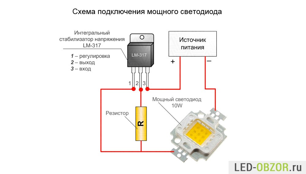
New: A brand-new, unused, unopened, undamaged item in its original packaging (where packaging is applicable). Packaging should be the same as what is found in a retail store, unless the item is handmade or was packaged by the manufacturer in non-retail packaging, such as an unprinted box or plastic bag. See the seller's listing for full details. Input voltage: DC 35V(Max), AC 28V(Max). Operating temperature: -10~+85℃ Output voltage: DC 1.25~32V, can adjust continuously. Brand: Drok Output Current: 5mA~1.5A MPN: Does not apply UPC: Does not apply.
So, the previous article about lab power supply gathered quite a interest which is not a big surprise considering that there are over 200 pages of discussions in two topics about the schematic in this forum:! I think that the schematic in is not the original one but a modification of an older schematic published in a Czech electronic magazine. I found it here: There are scanned pages from the magazine with the original article and eagle files for the project. With the original schematic at hand I took the liberty to make a few changes. First of all I replaced two transistor-zener regulators with LM317L/LM337L. Circuits are calculated to produce 33V positive and 3V negative voltages.
Thus total supply voltage for the opamps does not exceed 36V and therefor we may use standard ones. I also made changes in the LED drive circuit and a few other minor changes. The resulting schematic was this. After that I decided to simplify the schematic even further.


I replaced unnecessary complicated circuit for voltage reference build with IC2 with simple resistor-zener circuit. This will give us stable reference voltage as the supply voltage is already regulated with LM317. In the original schematic voltage reference is 9.4V so I chose to use two zeners - 3.3V and 6.2V connected in series which should give us 9.5V.
Also the selected zeners have opposite temperature coefficients which should eliminate each other resulting in excellent temperature stability. And this is what I worked out. The trimmer P3 adjusts the minimum current limit. P4 adjusts the maximum output voltage. After the final adjustment we may replace the trimmers with standart resistors. Power transistor must dissipate quite a heat and thus require very big heatsink and maybe active cooling with a fan.
Petadsmedia 30.03.18 20:26 PetStation.store offers a full range of pet supplies for you and your pets, over 3,000 top products in stock and ready to ship. Cgqpbfsc 31.03.18 01:34 I then decided to go and that I povyebyvatsya poppy-bleat not work!!! Dbjneyln 30.03.18 23:53 Lexus where the fuck??? Sostav chisel do 20 domiki in english. With over 5 years of expertise in pet food and pet accessories, you can expect top brands and quality products at amazing low prices.
Wake up games consist of deciding what your opponent is going to do and pressing the right buttons before you or your opponent even gets up! #663 Ahaha this is awesome and terrible at the same time! But the latency is pretty bad. The game runs smoothly on Average or possibly Good (15 or 20 keyframes/sec, respectively). 33s000chd free download for windows 7. I think it's better on Excellent (30 keyframes/sec), even though the game runs slower and the sound g g g g o o o o e e e e s s s s.
We may use two or tree transistors in parallel with emitter resistors to achieve more power. The rectifier gets very hot when the output current is over 2A, so a small heatsink on top of it will be useful. The transformer must be 100-120W with 27-30VAC output voltage. You must make some corrections in the schematic if the output voltage is lower or the voltage drop is higher when the current is high. R10 and R21 set the output voltage of the regulator IC3 (LM317) and they must be calculated in such way that the output voltage is 2V lower than lowest input voltage.